Aka: a long explanation of where all my money has gone.
Introduction
For a while now I have been steadily accumulating metalworking machines with the ultimate goal of being able to make model engines.
I feel like my workshop has finally reached the singularity where instead of buying tools I can actually make them, and it is time to showcase it.
_Editor’s note_: Please be warned, this post is long – you may wish to grab a cup of your favorite hot beverage – however if you don’t want to read you should be able to just look at the photos to get a gist of what’s going on.
My expensive story begins with this TIG welder from Token Tools
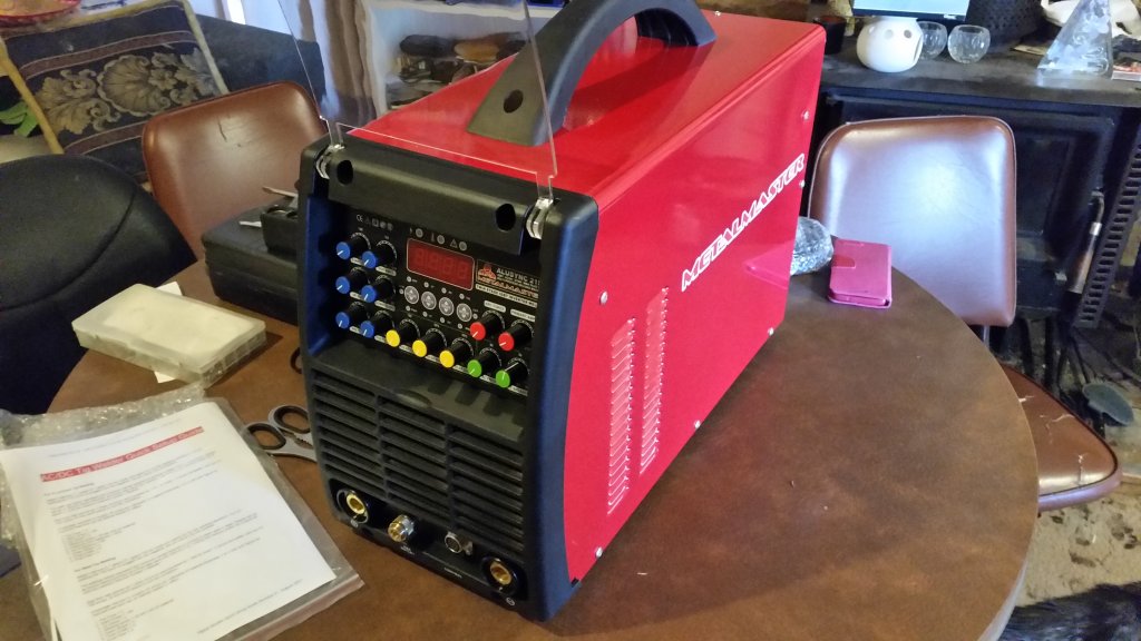
I chose TIG because I am a masochist. Might have also been because of This Old Tony. :)
Actually, there was a point in my life where I took a break from machining to learn welding in order to make a replacement battery tray for this old car I was trying to register. Mind you, said car was instrumental in the acquisition of more expensive machines, so it could be argued that the car was actually the seed of my bank account’s demise.
Anyway since I had this TIG welder, it naturally followed that I needed a grinder – for sharpening the tungstun, of course.
I attended a welding course where they had these 3 phase pedestal grinders made by Brobo-Waldown, which when you pressed the “on” button they were instantly on, none of this winding up business! As such I had to have one.
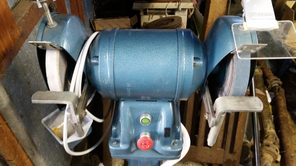
I didn’t let the fact they were 415v 3 phase deter me. I just needed a step up transformer and a VFD. Ironically, the VFD means it can’t be switched instantly on, oh well. At least it will probably last forever.
And since I now had a grinder, well, that meant I could grind lathe tool bits. So…
I was doing an idle google search one day and this lathe popped up (next to a Colchester Student that was way out of my league)
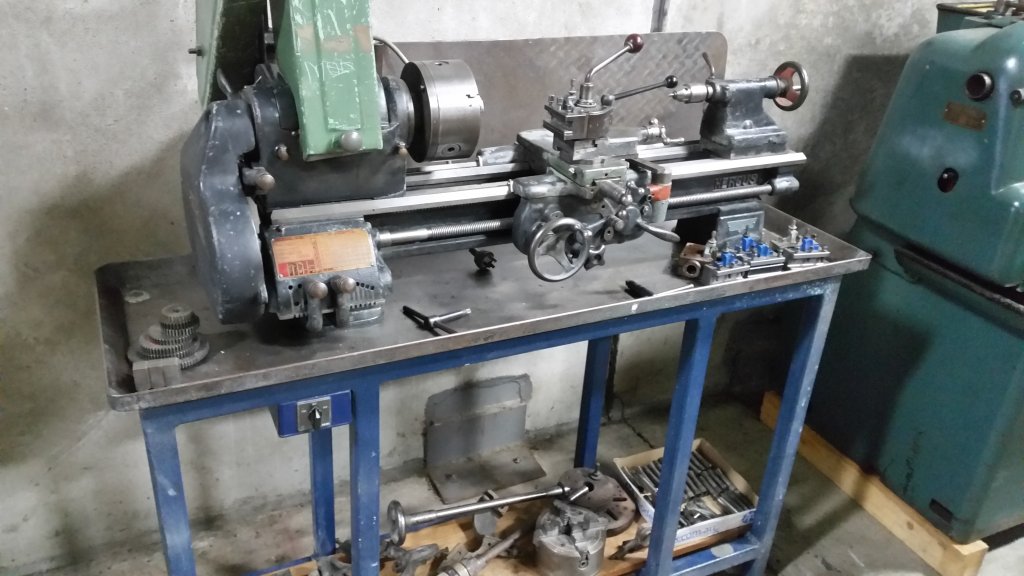
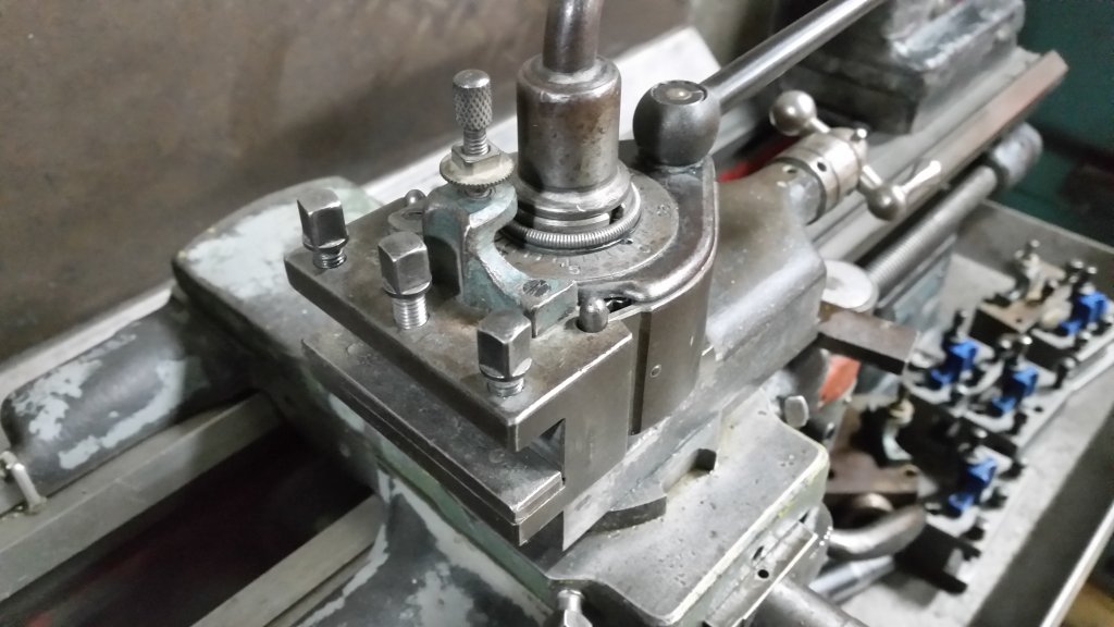
It was a Hercus 9 ARM that included a lot of tooling, including a rarish optional boring table which will be great for line boring. The next day I went and inspected it and ended up buying it. The ad had apparently been up for one whole day! Which explains why I was having such difficulty finding these things.
I had actually considered purchasing a Sheraton Conquest lathe a few weeks before, but the shear mass of the thing put me off. I don’t currently have direct access to the backyard shed, and getting to it is not easy, which the following pictures will demonstrate.
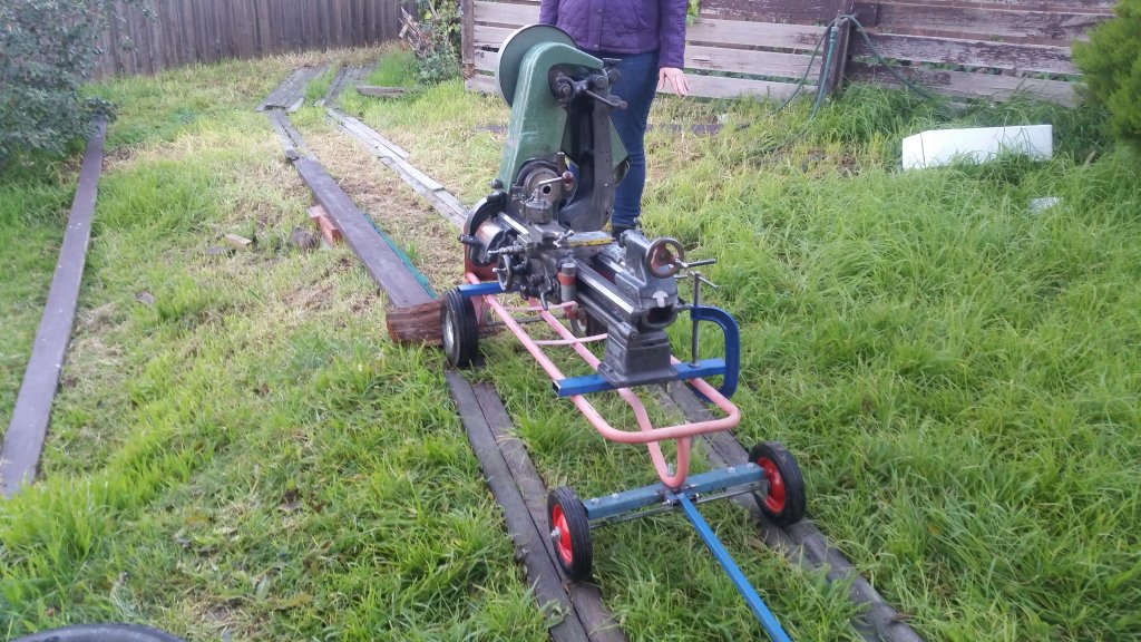
I have to go down the side of my house and then across a sloping yard. To make moving the lathe as easy as possible, I used a bunch of old planks from a deck to build a wooden railway of sorts.
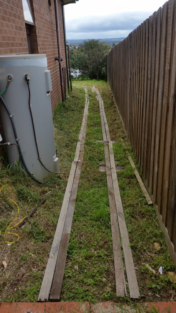
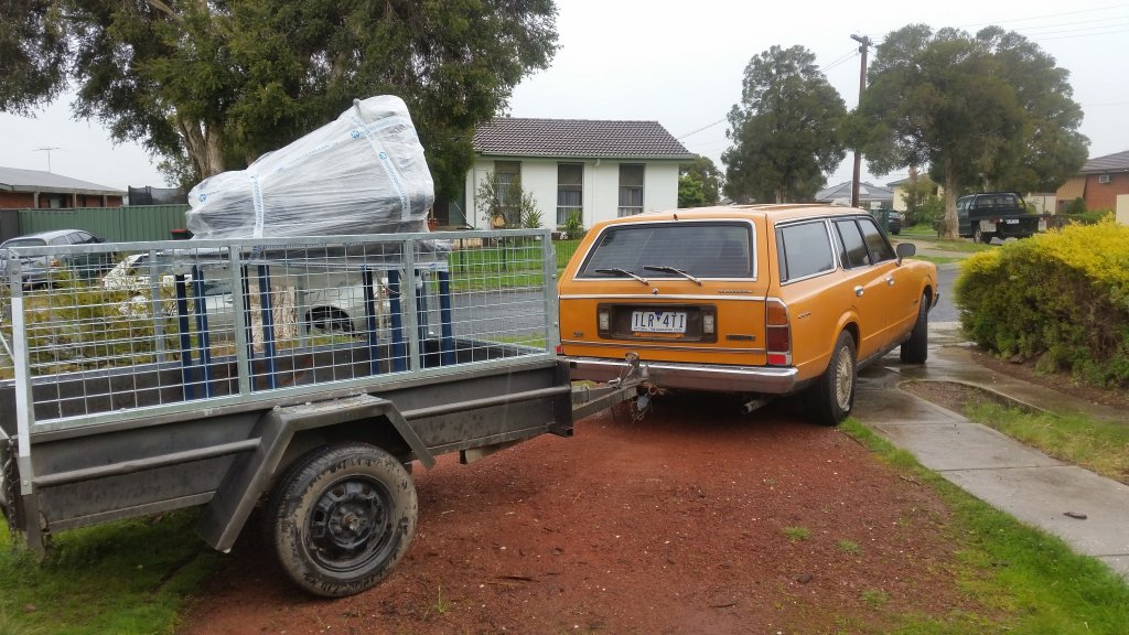
Thankfully this lathe’s table came with a levitation mode, but unfortunately a software bug meant it could only translate up and down.
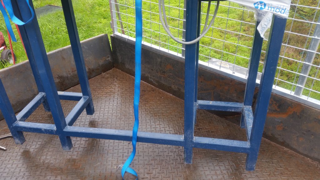
The lathe did have to be separated from the table
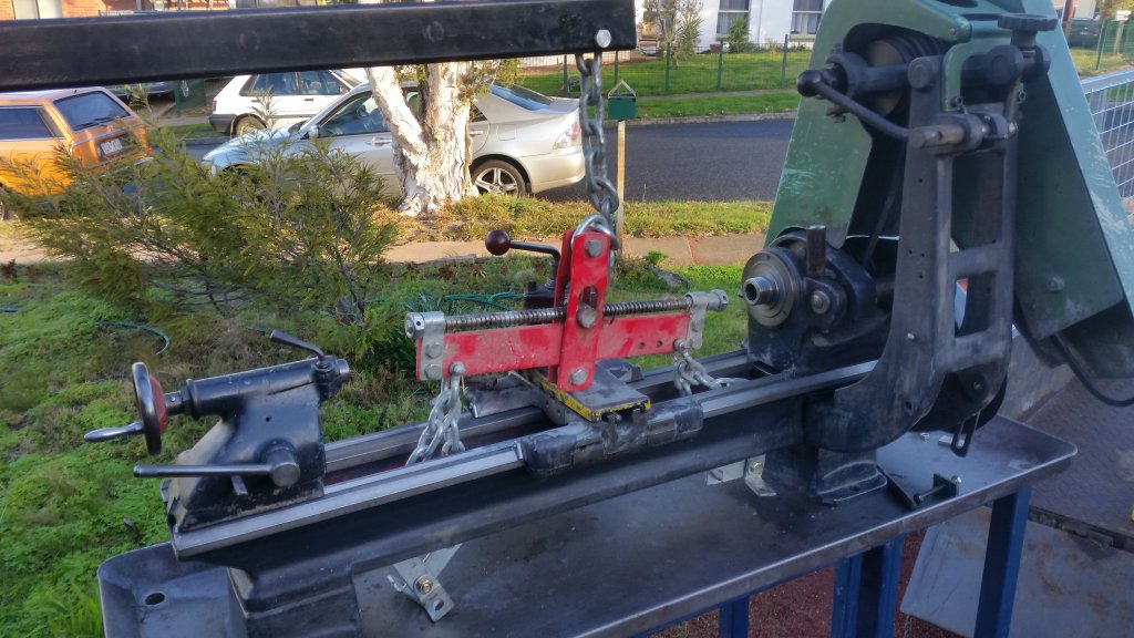
Assisting me is The Minister for Finance <3
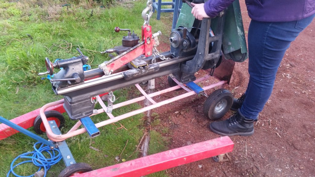
The trolley actually worked really well
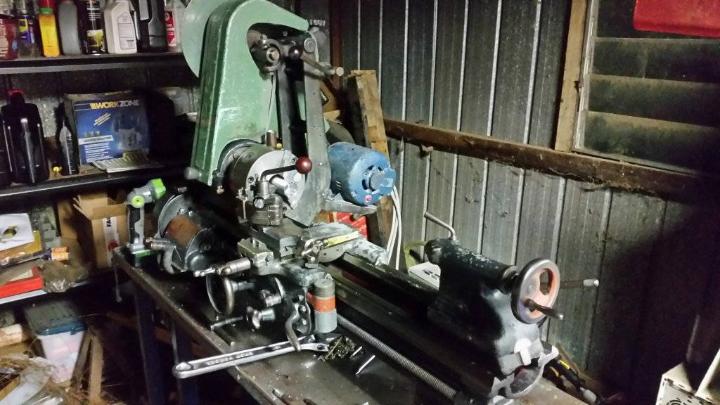
In it’s nearly final spot, where an old Piano had once sat (it came with the house when we bought it and had been savaged for most of it’s parts by the previous owners)
At this point, I decided that I had everything I needed, and a milling machine would be a “nice to have”, since I could do small milling jobs on the Hercus. Maybe a few years into the future.
Probably only a month later I started looking :D I managed to discover that Hercus made a horizontal milling machine. I also discovered that they were essentially rare, and that only the year prior several had sold at auctions for peanuts. To keep the Minister for Finance happy, I had decided that I would only have the Hercus Mill, and would keep an eye out.
A few years go by, and just as Melbourne goes into Lockdown #6, an ex-government Hercus Mill “3 slotter” appears in South Australia.
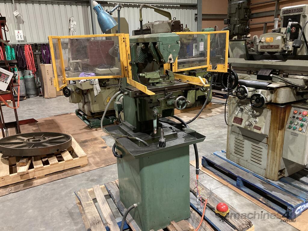
Thanks to the lockdown, I can’t be jumping in the car with a trailer and going off to check it out. Considering that they come up once every couple of years, I took a risk and bought it anyway. They had sent some video of it running but, I was essentially buying sight unseen. However, it was “cheap”, mostly because it lacked a lot of tooling and the vertical head attachment.
The best I could hope for is that students would be put off by the fact it was horizontal only and the machine will have seen light use.
And of course because the mill was cheap, I ended up adding a Vertex BS-0 dividing head, clamping kit, and vertex ER32 collet set.
One thing that blew my mind was that the cost of freighting from Adelaide to Melbourne was only $150! I was originally going to pickup with a trailer and the trailer hire alone would have cost that much let alone fuel.
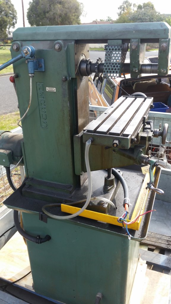
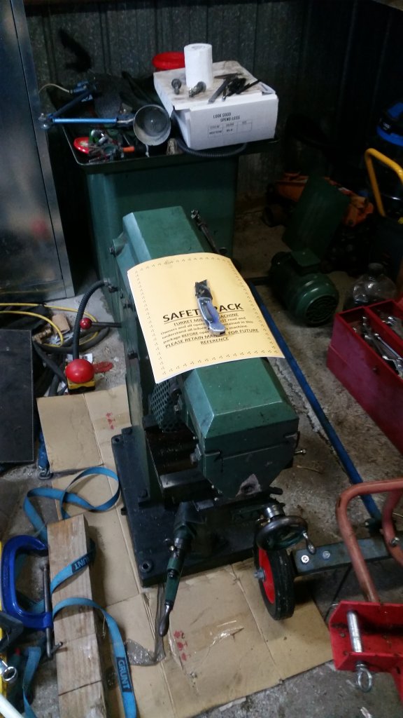
Collecting the Mill and getting it into my shed took all day. Mostly the getting off the trailer and into the shed part. There was a point I was worried that I would need a crane. This thing is heavy! I even had to extend the trailer hire to overnight because I feared I wouldn’t finish in time. As a matter of fact, I actually managed to finish with half an hour to spare -_-
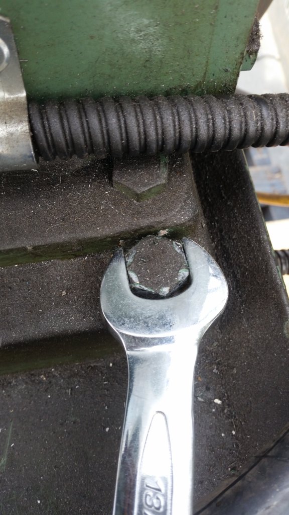
0 points to the operator who drilled that hole too close such that sockets won’t fit -_-
Unfortunately I had to split the mill from the base, which it was sealed. I did not take a photo here, but I had to assemble the engine hoist in the trailer because it was unable to reach in far enough to raise the mill from the base. Once separated, I was able to put the mill down and then it could be just reached with the hoist.
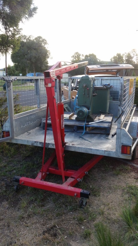
“And the golden light doth shine and the angels sang: Sun’s gettin’ pretty low, ain’t it?”
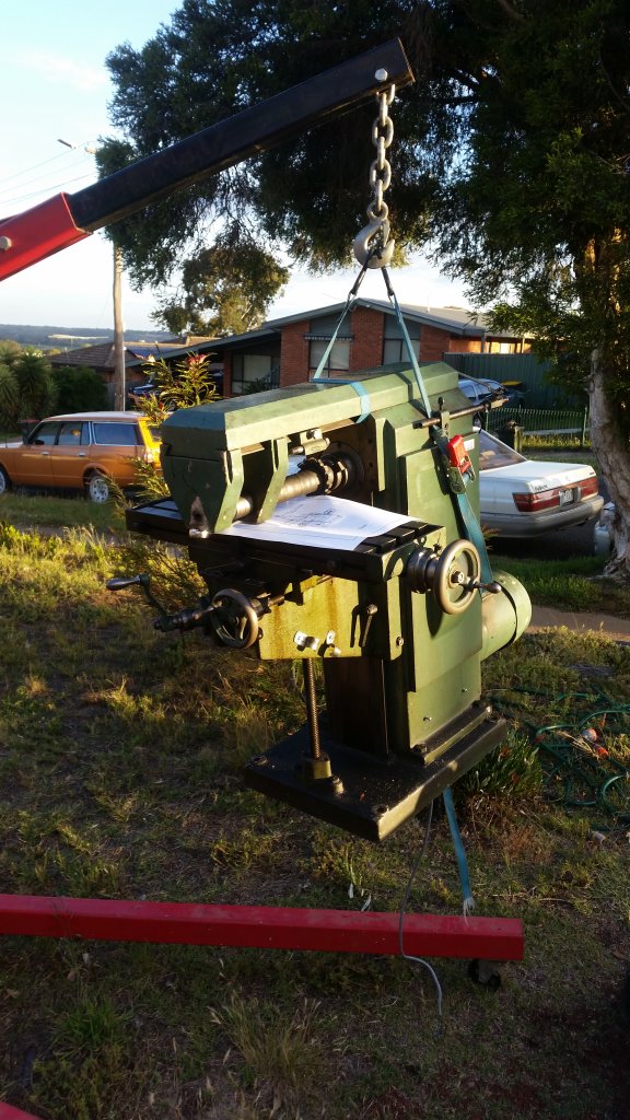
Also not shown is moving the mill, but lets just say the sun had well and truely set by the time I finally got it into the shed. I will reiterate that the thing is darn heavy!
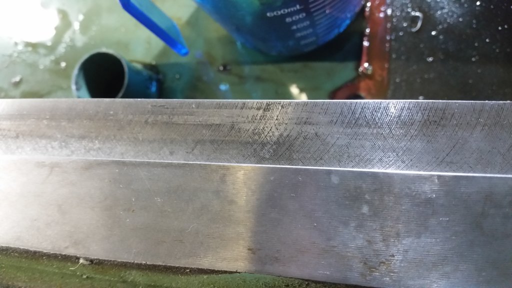
Since I had to dismantle a lot of it, I did get a look at the ways. I could still see the factory machining and scraping marks, which I took as a good sign.
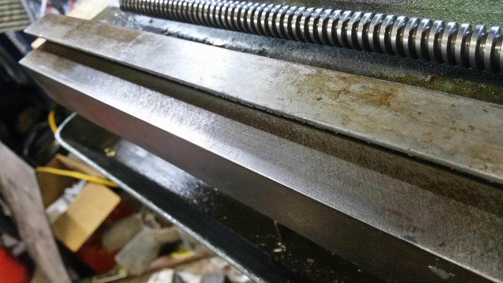
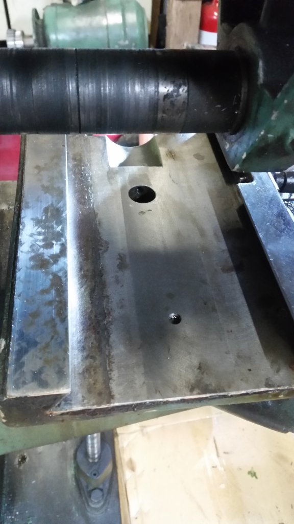
One bad sign however is that grease had been used where oil was supposed to be used. There was at least evidence oil had been used in the main spindle bearings, but everything else including the backgear pulley had been pumped with grease. At some point I’ll probably have to do what [url=http://”https://www.youtube.com/watch?v=smlSD1gggWk”]this guy has done[/url] and take the spindle out to check everything. His mill does sound quieter.
One of the things I did notice is the horizontal arbor seemed stuck, a drawback of the Morse Taper design. After trying various drifts and tapping on the drawbar with a hammer and trying not to hit too hard, I had read about other people’s experiences with this machine and there seemed to be two schools of thought: 1) Hit it really hard 2) Create a puller
I had noticed the end of the drawbar nut was expanded so obviously someone tried the first strategy at one point. And there was also the concern of potential damage to the bearings due to heavy impacts. I ended up creating a puller from a 10mm flat bar (and of course, the astute reader may have noticed the second set of tapped holes - that would be of course because I didn’t measure properly and the nut heads didn’t clear the arbor shaft)
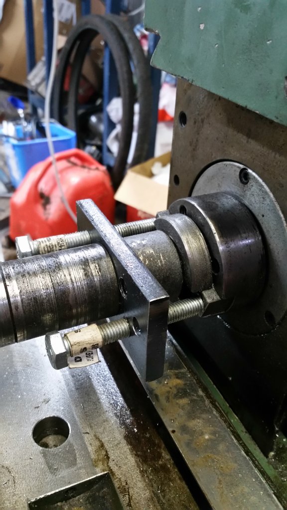
I am glad I went this route because it took a tonne of force (no really) to get the arbor to release, the 10mm bar actually bent and I thought I was going to have to get something even thicker, but it did finally budge. Someone had really done the drawbar up tight.
The table seemed to have slop it it and was binding at the ends, not surprising since most of the work would have been in the centre, reading about 1 thou in the centre and more than 5 thou from centre to end. I thought I had bought a dud after all, but I read up on adjusting the gibs and realised that 5 thou play was coming from the table rocking on it’s saddle as it moved from one side to the other. I also realised that the taper gib in the X axis was installed very badly and at some point had been dropped, which is why it binded on the far left but was sloppy to the right.. Once deburred and installed correctly, and the Z and Y gibs re-adjusted all slop was pretty much eliminated and the movement of the X axis is smooth and less than 0.5 thou almost end to end, with the dip occurring in the centre. The table movement is also smooth until the extremes.
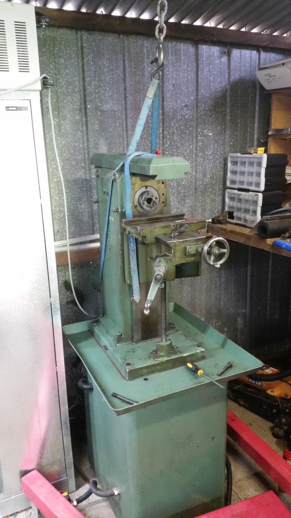
At this point my bank account thought it might finally breathe a sigh of relief but a few months later :D
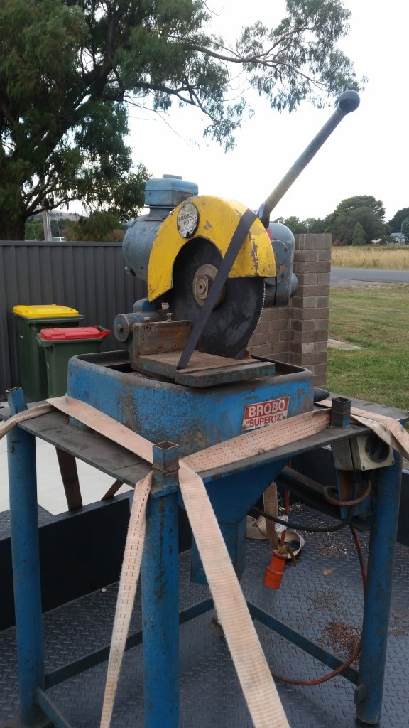
I found this Brobo Super 12 for “cheap”, which in hindsight could have been significantly cheaper, or perhaps if I just waited a bit longer as an identical model that was cheaper and in better condition came up for sale a few months later -_-
It appeared to have a life in a factory cutting a lot of copper, and I am certain that every bolt on it has been stuffed, as I found out later. The ability to rotate for mitre cuts was completely seized, which took quite a few evenings to sort out.
The thing is heavy, apparently massing 135kg. It wasn’t difficult getting into the shed, but it was difficult getting it reassembled. I can also vouch for these things being incredibly strong because I managed to drop the motor-gearbox portion from a height of about 1.5 meters onto concrete because the hoist wasn’t set on the floor properly. Luckily the blade was removed and it fell on it’s right side where it broke the concrete where it landed.
Upon reassembly it was making an unhappy grinding noise, which I can’t say for sure wasn’t already there because my memory of the test run was already hazy. With the front bearing cap removed, the grinding noise is gone but I could see maybe a 0.1mm wobble in the worm shaft. Not good. The grinding noise appeared to be coming from said front bearing cap, indicating it was stuffed.
At any rate, I had no choice but to take it apart and see if anything was bent. From what I could measure, there was a maximum of 0.05mm runout in both the motor shaft and the worm shaft. Oddly, when everything is reassembled, the wobble in the worm drive is back. Operation doesn’t appear to be affected so I’ll try replacing the front bearing and see how it goes.
OK, if you haven’t stopped reading by now you are probably wondering if I have managed to actually do anything with these machines?!
Unfortunately, nothing yet to do with model engine making, but here are a few projects:
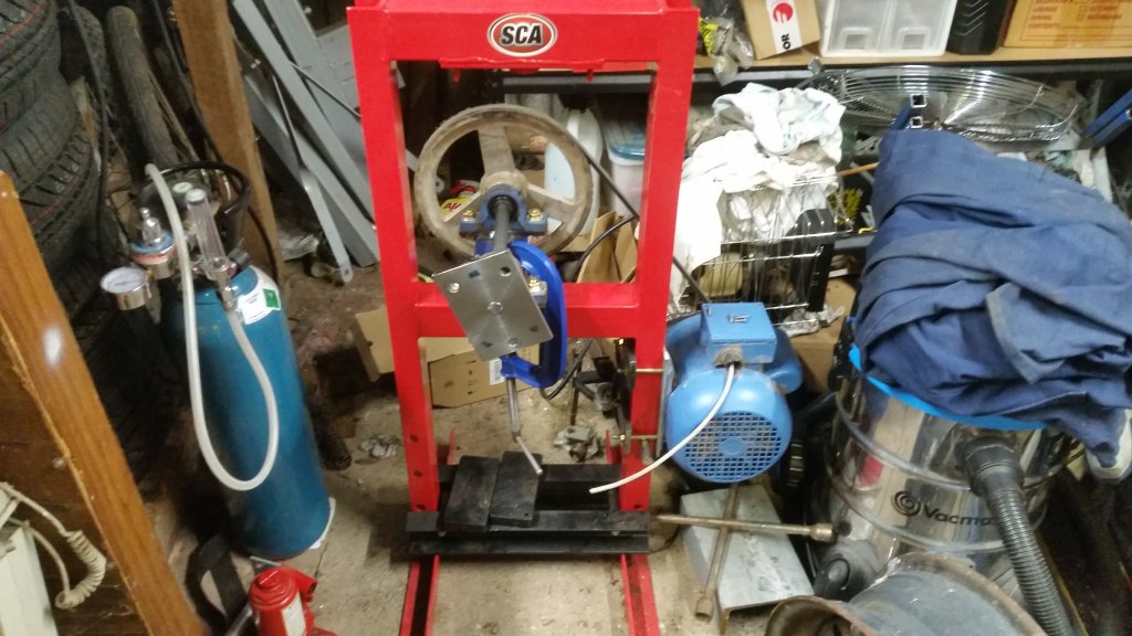
The “Wheel Spin-o-Tron 3000”
A dangerous alternative to sand-blasting (technically the opposite of sand-blasting). Seriously, unless you just happened to have all the materials and equipment plus a machine shop at your disposal, you are better off just paying the $50 per wheel I think I was quoted.
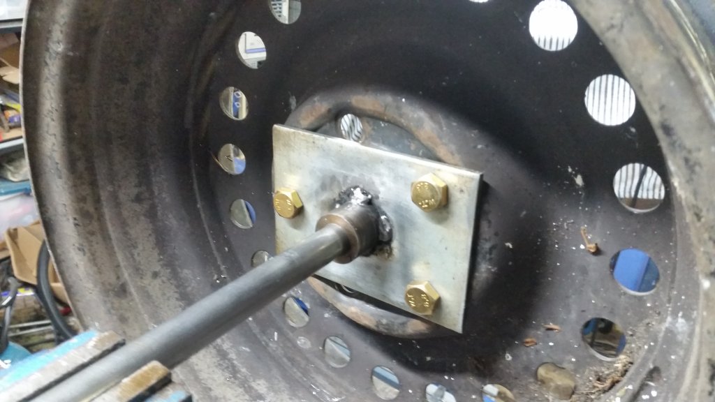
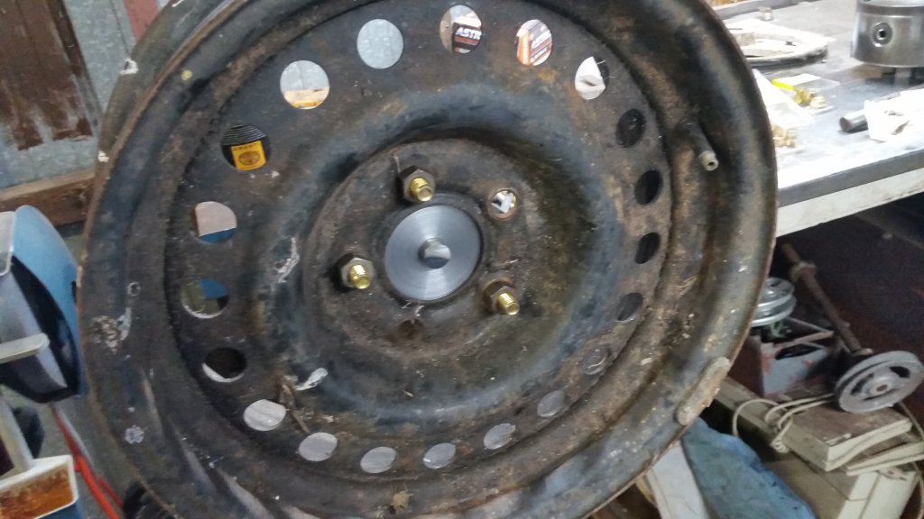
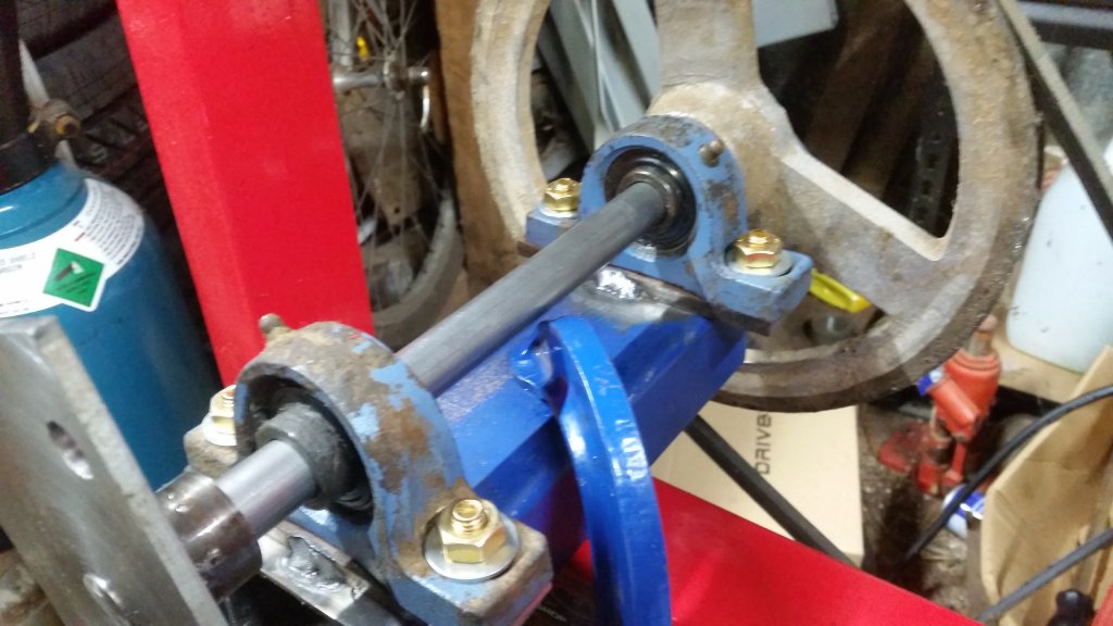
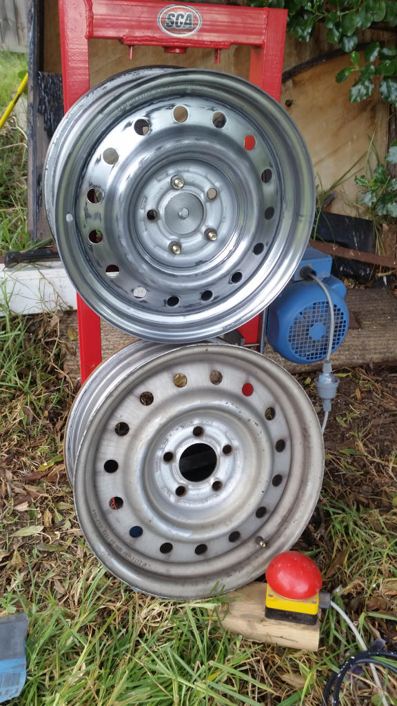
The Repacement Dust Cap aka “Even The Government Is Laughing” Project
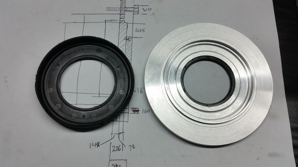
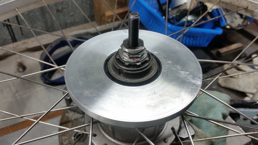
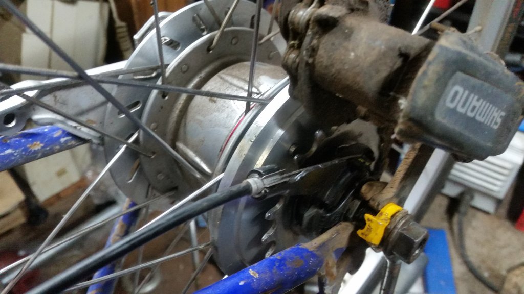
My bike has a Shimano Nexus 8 internal geared hub which needed a new dust cap.
I could have purchased a replacement online for about $20, but instead I thought it was better learn how to machine a replacement out of aluminium1, which necessiated purchasing my own lathe and tooling to go with it. A process which took over 7 years.
Part of the reason this project took me so long was working out the order of machining steps (aside from having to learn how to use a lathe first). The original dust cap had a labrinth style dust cap that in the end I just decided not to bother including.
The Disk Brake upgrade for Victorian Railways era H Type Rail Inspection Bike
My Step Dad acquired a “fairly rare” rail inspection bike, which uses a wooden block as a brake. I say “fairly rare” since he managed to get a second one only a year later, although that is because he works for the railways.
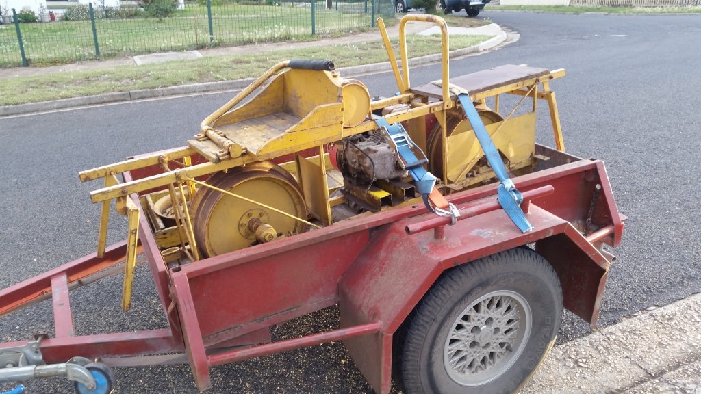
As a means of “improving safety” he found a dual disk brake kit online and tasked me with coming up with a way to retrofit them to the rail bike. I came up with an adapter that mounts the disk to the wheel’s hub.
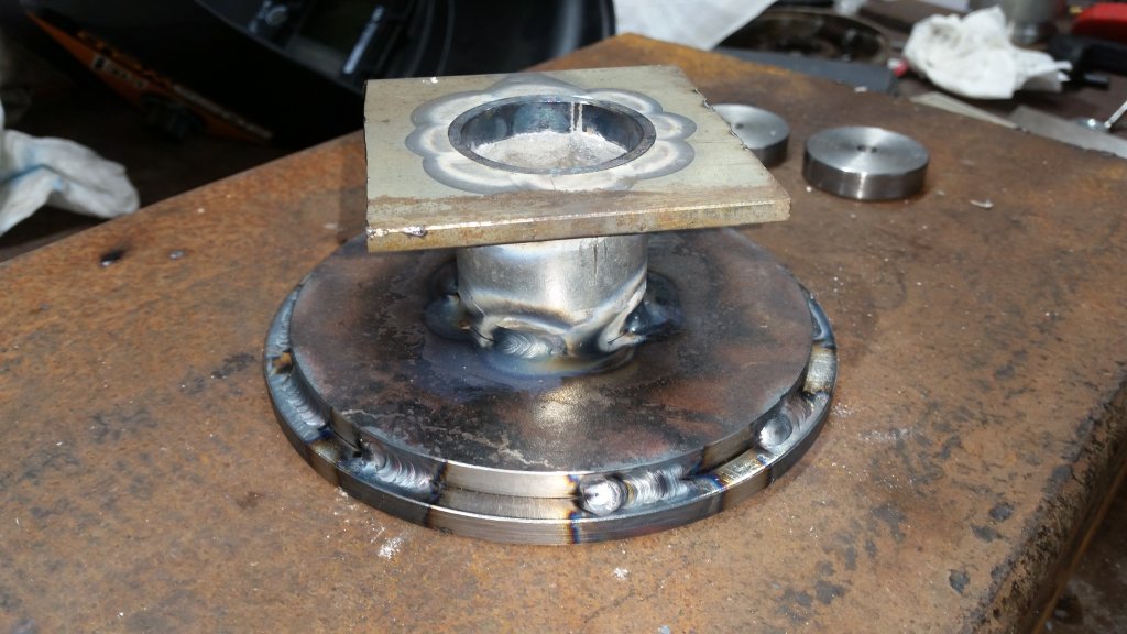
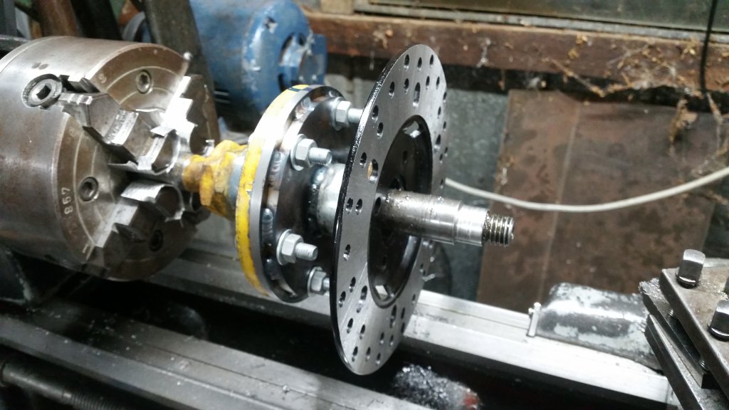
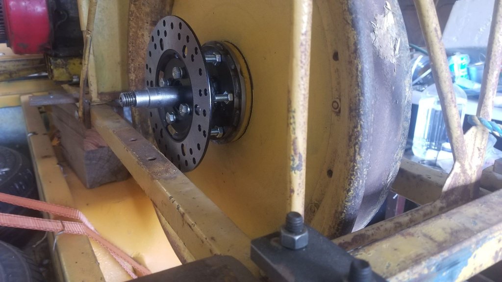
To be honest, I am sure the wooden brake is more than sufficient, and I predict that when we first apply the disk brakes that the wheels will just immediately lock up (assuming nothing breaks, of course).
This was actually a fairly challenging project that involved a lot of measuring, planning, modelling and some tricky machining order of operations. I am still in the process of fabricating the bracket that will hold the caliper.
If you made it this far, thank you for taking the time to read :)
-
since the reason the dust cap needed replacing in the first place was I used some gear oil which warped the plastic. ↩