Nearly two years ago my Step Father purchased one of the few Victorian Railways era H Type rail inspection bikes. Only a year later he managed to score a second one, but that shouldn’t be surprising since he works for the Railways.
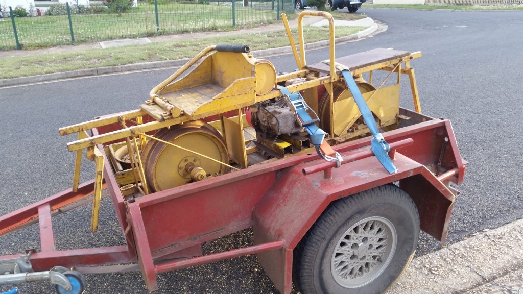
As a means of “improving safety” he found a dual disk brake kit online and tasked me with coming up with a way to retrofit them to the rail bike. I came up with an adapter that mounts the disk to the wheel’s hub.
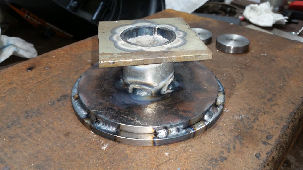
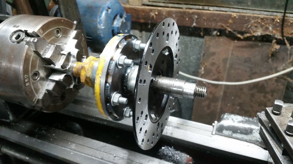
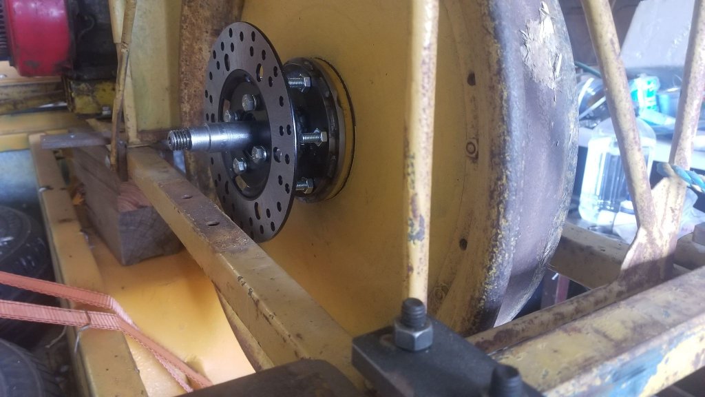
This project has finally got to “minimum viable product” stage … i.e. only the front wheel has been converted. (facepalm)
After completing the hub I had to figure a way to mount the brake master cylinder, attach a lever to it, a bracket to mount the brake caliper and other hardware.
The rail bike has a wooden block for a brake that is attached to a square spindle which is actuated by a long lever; the brake handle. Pulling back on the brake handle engaged the wooden brake block. Luckily for me there was enough room and movement in the forward direction of the brake handle that I could essentially attach the disc brake master cylinder to it so that pushing forward would engage the disc brakes, and if necessary, pulling backwards would still engage the wooden block. Not only that, but the bike frame had a convenient place to mount the master cylinder. The parts are shown below:
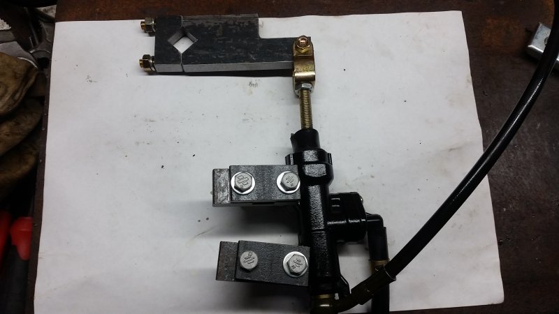
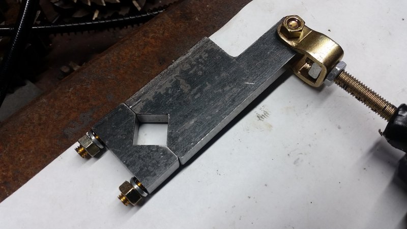
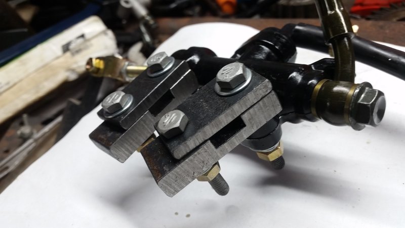
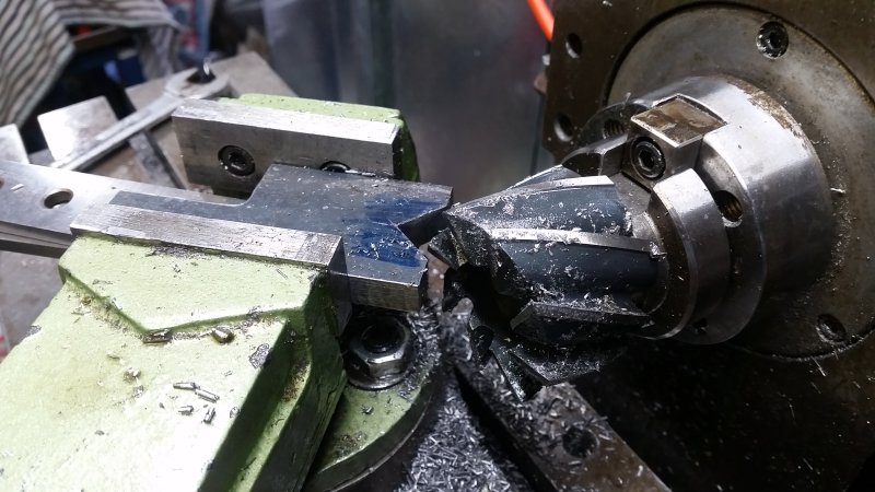
I must say that the Hercus mill had no trouble chomping through the 10mm thick bar to form the squares. (You can read about my machines here)
Here is the hardware mounted
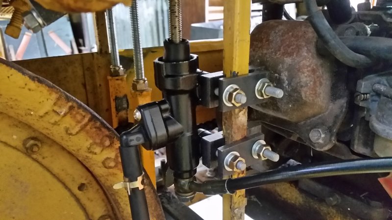
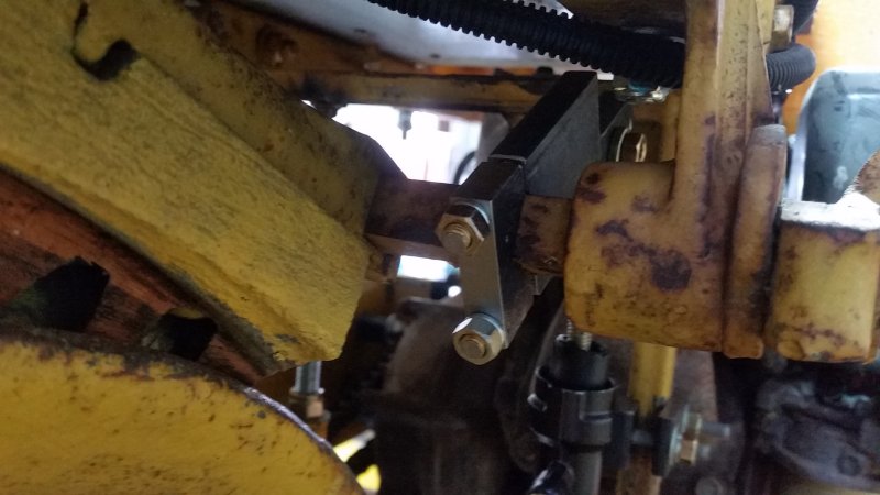
I have access to the original VR drawings, but that still didn’t stop me from technically messing up the master cylinder lever.
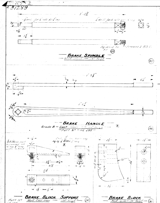
From the above diagram it can be inferred that when the brake handle is vertical, the wooden brake block will be 45 degrees. I had thusly designed my master cylinder lever to be horizontal when the brake lever is vertical, therefore I had to go to the effort of cutting a V shape into the brake lever. This design allowed both the disc brakes and original wooden block to co-exist.
The only problem with that idea is that for the master cylinder brake lever to be horizontal, the wooden block would be pretty much crashing into the top of the bike frame, preventing the brake handle from being pushed forward (facepalm)
I lucked out though – there was enough room in the frame for mounting the master cylinder up higher so that the master brake lever lever would be 45 degrees up (and nearly horizontal when fully engaged), but the wooden block would not be also engaging the wheel.
The next problem is that the brake cylinder lever was too long! I had forgotten to account for the brake cylinder being mounted about 15mm to the left of the frame… well as they say, if you can’t make a part with precision, make it adjustable (facepalm) you will see in the below photo that the hole was re-drilled closer on the master cylinder brake lever.
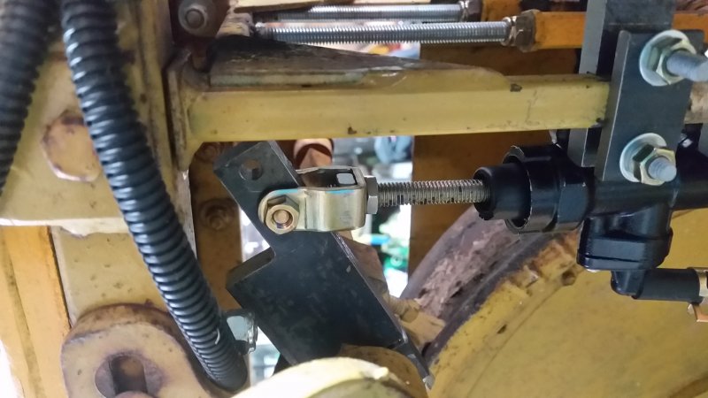
And here is the brake caliper mounted. The bracket is just 5mm thick flat bar welded at ~72 degree angle to the horizontal. It is mounted via the original bearing hub bolts which go through the frame.
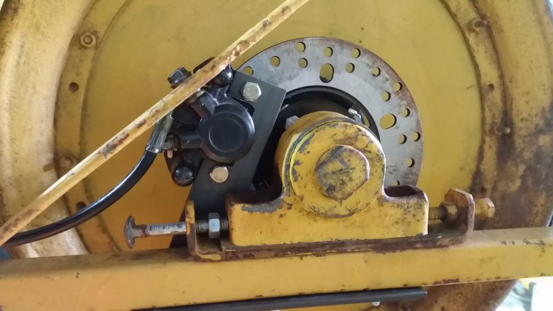
I spent so much time drawing up and modelling the caliper bracket. From the drawings the angle needed to be about 72 degrees to clear everything. In the end, I just ensured the brake caliper engaged the disc by compressing the brake cylinder, and scribed the angle that made in relation to the frame. Came out to be about 72 degrees. Yeah sure I managed to predict that, but without a good origin reference, there was no way I could have fabricated that bracket from drawings alone. In 5 minutes I could have had my answer (facepalm)
Anyway, thanks for reading!